Bringing up GMSL2 cameras
From a connected camera head to the first image: three steps for three different starting points.
Bring-up
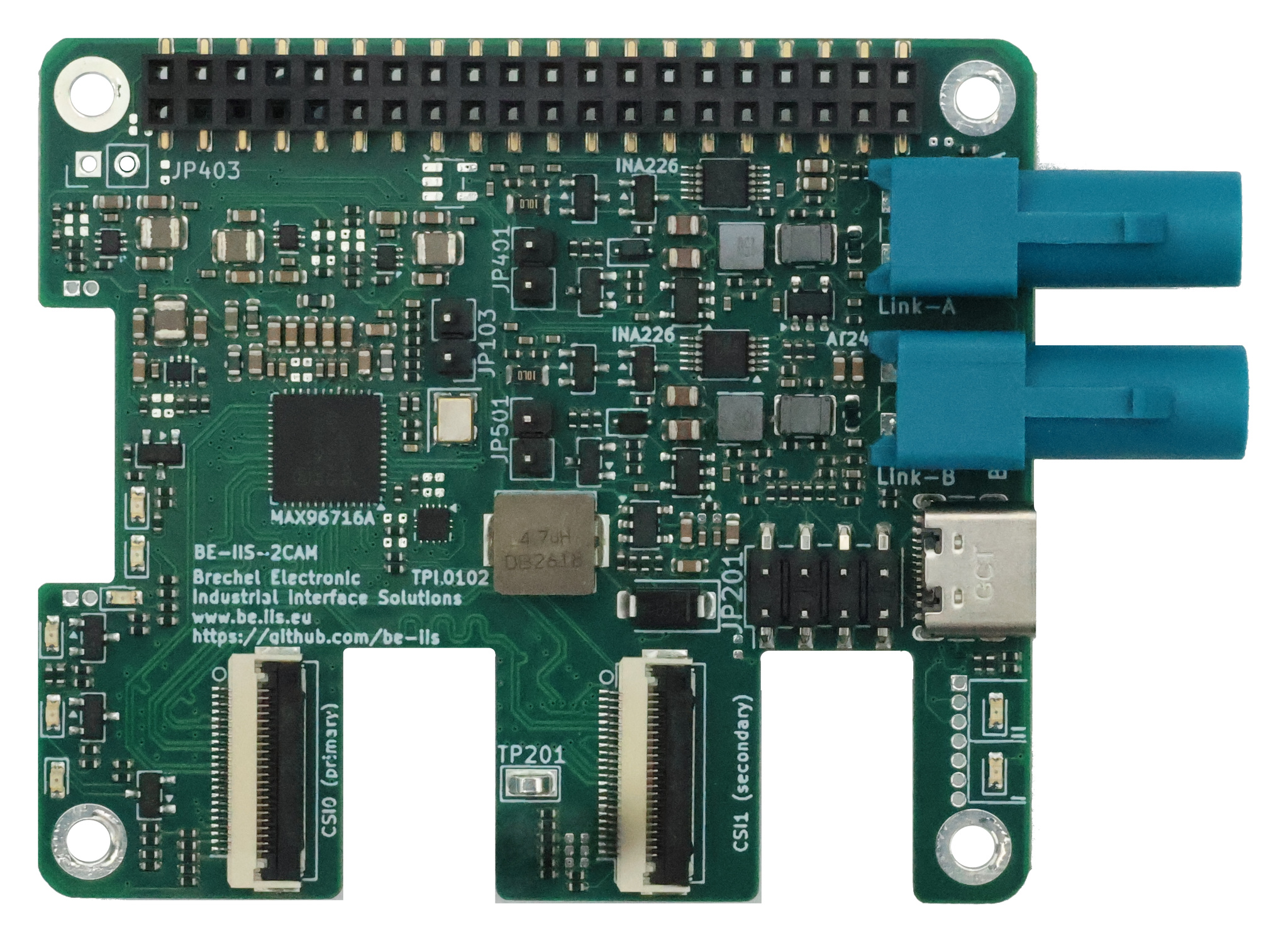
This guide is part of the BE-IIS-GMSL2-2CAM HAT documentation. Choose the section for your setup:
- HAT with a matching serializer and imager: Configure the Pi and capture the first image using matching components.
- New imager on the BE-IIS serializer: Keep the serializer and adapt sensor control and video settings.
- Another GMSL2 camera: Integrate a complete camera with its own serializer.
Each section follows the same three steps:
- Connect the hardware.
- Establish the I²C path.
- Establish the MIPI path.
Two paths with different jobs
The I²C path provides control. The Pi accesses the HAT’s deserializer, the remote serializer through the GMSL reverse channel, and finally the sensor. This path carries sensor identification and controls such as exposure and operating mode. Reaching the serializer does not yet prove that the sensor is reachable.
The video path carries images. The imager sends MIPI CSI-2 to the serializer, which transports it over GMSL2 to the HAT. The deserializer outputs MIPI CSI-2 to the Raspberry Pi. The sensor driver starts streaming when the camera is opened.
An entry in rpicam-hello --list-cameras confirms discovery. Only received images confirm the complete video path.
Case 1: BE-IIS HAT with a matching serializer and imager
This example uses a Raspberry Pi 5, BE-IIS-GMSL2-2CAM Rev. B, BE-IIS serializer with MAX96717 and IMX708. The serializer and matching imager are already connected. Start with one camera on Link A.
The commands match the installer revision linked below. Its imx708-revb profile is marked verified, but the README explicitly requires a hardware retest of the migrated JSON initialization before production use. This article is not a new hardware test report. Other board revisions and sensors require an appropriate, tested profile.
1) Connect the hardware
- Switch off the Raspberry Pi and camera supply.
- Mount the HAT and connect the CSI output assigned to Link A to the Pi 5’s CSI1 input. Check FFC contact orientation and connector locking against the board markings.
- Connect the assembled serializer and imager to Link A with the appropriate coaxial cable.
- Configure the supply, including Power over Coax, for the board revision and camera head. Voltage and power requirements must match at both ends.
- Switch on and boot Raspberry Pi OS.
For the dual reference setup, connect a second matching camera head to Link B and its CSI output to CSI0 on the Pi. This mapping applies to the reference configuration described here.
2) Establish the I²C path
Enable the Linux I²C interface
Linux must expose the I²C controller first. On current Raspberry Pi OS, open:
sudo nano /boot/firmware/config.txt
Older images use /boot/config.txt. Edit the file present on your system. Set the following entries in the effective [all] section, updating existing settings where necessary:
[all]
dtparam=i2c_arm=on
dtparam=i2c_csi_dsi=on
camera_auto_detect=0
i2c_arm enables the ARM I²C interface on the GPIO header. The camera bus used here additionally requires i2c_csi_dsi. Disabling camera_auto_detect avoids conflicts with the manually loaded camera overlays.
Reboot after making changes:
sudo reboot
Then install the tools and load the userspace interface:
sudo apt-get update
sudo apt-get install -y i2c-tools
sudo modprobe i2c-dev
i2cdetect -l
ls -l /dev/i2c-11
i2cdetect -l lists adapters without scanning devices. These examples use bus 11 on the reference Pi 5 configuration. If it is missing, check boot settings and the CSI connection first. Bus 1 is not a substitute.
Reach the HAT’s deserializer
Probe the expected DES address, then read its identification register:
sudo i2cdetect -y 11 0x28 0x28
sudo i2ctransfer -y 11 w2@0x28 0x00 0x0d r1
A scan result of 28 means a device responded; -- means no response. UU indicates that a kernel driver owns the address. Resolve driver ownership instead of forcing access with -f. Scans send bus transactions too: restrict them to known addresses here and run them before loading camera overlays.
w2@0x28 sends the register address bytes 0x00 0x0d; r1 then reads one byte. This selects register 0x000D without writing a new configuration value.
Checkpoint: Bus 11 exists and the DES responds to a targeted register read. Proceed to the remote serializer only after this works.
Install drivers and initialization tools
Install the software on the Pi:
git clone https://github.com/be-iis/be-iis-cam-installer.git
cd be-iis-cam-installer
PROFILE=imx708-revb
./install.sh "$PROFILE"
For an existing checkout on main, update with git pull --ff-only origin main before installation, provided there are no unresolved local changes.
The installer sets up dependencies, drivers and Device Tree overlays. If it needs to change the boot configuration, it reboots the Pi. Return to the repository afterwards, set PROFILE=imx708-revb again and rerun ./install.sh "$PROFILE". Installation alone does not activate a GMSL link or video pipeline.
Checkpoint: Installation completes successfully and finds the camera I²C bus at /dev/i2c-11. Do not assume I²C bus 1 for this reference configuration.
Initialize the remote I²C path
Stop running camera applications. From the installer directory:
PROFILE=imx708-revb
make unoverlay
make init-a PROFILE="$PROFILE"
unoverlay removes dynamically loaded BE-IIS camera overlays. It does not remove static overlays in the boot configuration; these must not conflict with manual setup.
init-a selects Link A, establishes serializer access, synchronizes the GMSL rate and runs the profile’s sensor power and enable sequence. It then configures I²C aliases and checks sensor identity and focus access. It does not configure the video path.
| Device | Reference I²C address |
|---|---|
| MAX96716A on the HAT | 0x28 |
| MAX96717 on the selected link | 0x40 |
| IMX708 locally at the serializer | 0x1a |
| IMX708 as accessed by the Pi, Link A | Alias 0x52 |
| Focus controller as accessed by the Pi, Link A | Alias 0x5c |
These are 7-bit I²C addresses. Two identical sensors can retain the same local address while the Pi reaches them through distinct aliases. Address-translation registers may encode addresses differently; use the matching profile’s implementation.
Checkpoint: Initialization completes without errors and reports a verified IMX708 at 0x52. GMSL link lock or an I²C scan alone is insufficient. If the sensor ID is wrong, check supply, clock, reset and address translation first.
Check the serializer and sensor with i2ctransfer
Run these commands after successful make init-a and before loading the camera overlay. Link A is selected, the sensor is powered and its aliases are configured.
# Serializer on the selected link
sudo i2cdetect -y 11 0x40 0x40
sudo i2ctransfer -y 11 w2@0x40 0x00 0x0d r2

# IMX708 through its host alias
sudo i2cdetect -y 11 0x52 0x52
sudo i2ctransfer -y 11 w2@0x52 0x00 0x16 r2
The current profile expects 0xbf 0x06 from the serializer and 0x07 0x08 from the IMX708. The sensor transaction reads two bytes starting at 0x0016. Do not expect these responses before initializing the link and enabling the sensor.
Writing a register: On the MAX96717, data follows the two register-address bytes. These commands demonstrate the profile’s sensor-address translation for Link A, reapplying the mapping already set by init-a:
# Host alias 0x52, encoded in the SER register as 0x52 << 1 = 0xa4
sudo i2ctransfer -y 11 w3@0x40 0x00 0x42 0xa4

# Real sensor address 0x1a, encoded as 0x1a << 1 = 0x34
sudo i2ctransfer -y 11 w3@0x40 0x00 0x43 0x34

# Verify translation by reading the sensor ID
sudo i2ctransfer -y 11 w2@0x52 0x00 0x16 r2
w3 sends three bytes: register-address high byte, low byte and one data byte. These writes apply only to the MAX96717 on the selected Link A. They do not replace link initialization or sensor supply, reset and clock setup.
When two serializers share an address, select the intended link before direct serializer access. Do not run these examples unchanged after dual-link initialization.
3) Establish the MIPI path
For the single IMX708 camera, load only the installed Link-A overlay, then configure video:
sudo dtoverlay imx708-gmsl-link-a
make pipeline-a PROFILE="$PROFILE"
rpicam-hello --list-cameras
The overlay describes the sensor, I²C alias, clock supply and CSI endpoint to Linux. pipeline-a configures the serializer’s CSI input and the deserializer’s output and routing. Both must match the sensor mode.
Select the camera index actually listed. With one discovered camera, this is usually 0:
CAMERA=0
rpicam-hello --camera "$CAMERA" --timeout 0
Stop the preview with Ctrl+C. To capture without a local preview display:
rpicam-still --camera "$CAMERA" --nopreview --timeout 1000 --output test.jpg
Checkpoint: The camera is discovered and produces a correct image. The documented IMX708 reference includes a 2304 × 1296 RAW10 mode with two CSI-2 lanes at 900 Mbit/s per lane. This CSI data rate is distinct from the GMSL link rate.
Extension: two matching cameras
With both camera heads and both CSI connections attached, use this sequence instead of the single-Link-A procedure:
PROFILE=imx708-revb
make unoverlay

# Both I²C control paths
make init-a-b PROFILE="$PROFILE"

# Linux camera registration and MIPI video paths
make overlays-a-b PROFILE="$PROFILE"
make pipeline-a-b PROFILE="$PROFILE"
rpicam-hello --list-cameras
Test each camera separately, stopping the first preview before starting the next:
rpicam-hello --camera 0 --timeout 0
rpicam-hello --camera 1 --timeout 0
The documented dual setup maps Link A → alias 0x52 → CSI1 → camera 1 and Link B → alias 0x53 → CSI0 → camera 0. Still check the current camera list for the actual indices.
Manual configuration can be lost after reboot or hardware reset. Repeat I²C initialization, overlay loading and pipeline setup when needed. The installer does not create an automatic camera initialization service.
Case 2: A new imager on the BE-IIS serializer
Keep the HAT and serializer, but replace the sensor module. The new imager may require different supplies, reset sequencing, clocking or CSI-2 output settings. A connector that physically fits does not establish electrical compatibility.
1) Connect the hardware
- Switch off the Pi and camera supply.
- Compare the new module’s pinout and electrical requirements with the serializer: supply rails, I²C levels, MCLK, reset, enable and CSI lane count and order.
- Attach the module using a suitable cable or adapter. Start with only one camera link.
- Choose the required sensor mode: resolution, frame rate, RAW/YUV format, bit depth, lane count and link frequency.
Keep the sensor datasheet, module schematic and Linux driver documentation available.
Checkpoint: The module can operate with the correct supplies, clocks and control signals.
2) Establish the I²C path
The path as far as the BE-IIS serializer remains broadly the same. Adapt what follows to the new sensor:
- Establish the GMSL link and serializer access.
- Apply supply, MCLK, enable and reset in the sequence specified by the sensor.
- Map the real sensor address to a unique host alias.
- Read its documented identification register and compare the expected sensor ID.
- Account separately for a focus controller and any other required I²C devices.
Camera-specific settings belong in a separate JSON profile, with matching DTS overlays for Linux:
| Area | Settings to review |
|---|---|
sensor |
Name, real address, ID register and expected ID; focus settings where supported |
links.a / links.b |
Unique sensor and focus aliases |
pipeline.sensor_power |
Supply, clock, reset and delays |
install.driver_target |
Appropriate driver build target, or none for an existing kernel driver |
overlays |
Device Tree files for the new sensor |
Current installer limitation: The runner expects two link definitions and shared sensor settings. Sensor identification uses a 16-bit register address, and a focus-controller access is mandatory after the sensor-ID check. A fixed-focus module without that controller or a sensor with another register protocol therefore also requires runner and validation changes. Different imagers on A and B cannot be configured merely by replacing a sensor name.
Copying a profile and setting status to verified does not validate hardware. Integrate new hardware in a controlled development setup and test it before marking it verified. The current runner only accepts profiles carrying that status.
Checkpoint: The correct sensor ID can be read repeatedly through the host alias, including after a complete power cycle.
3) Establish the MIPI path
Align the complete chain with the chosen sensor mode:
| Part of the path | What must match? |
|---|---|
| Sensor driver | Register initialization, mode, stream-on/stream-off and format |
| Sensor → serializer | Lane count and mapping, CSI clock and data rate |
| Serializer → deserializer | GMSL mode, stream assignment and supported bandwidth |
| Deserializer → Pi | CSI output, lane count, data type and virtual channel where applicable |
| Device Tree | Driver compatible, I²C alias, clocks, supplies and connected CSI endpoints |
Profile video sequences include serializer_csi, deserializer_a, deserializer_b, route_a and route_ab. Their register settings must match the actual hardware combination.
The IMX708 driver and overlay do not replace a driver for a different sensor. The chosen libcamera/rpicam system must support the new sensor, with suitable image-processing parameters where required.
Once the profile, runner support, driver and overlays have been implemented and checked, follow the sequence from Case 1 with the new profile and its overlay names. Do not try the IMX708 profile on an unrelated sensor.
Checkpoint: Discovery, capture and repeated stream starts work in the intended mode. Check format, colour, resolution and stability. Existing make png and make video helpers contain IMX708 resolution settings and need reviewing for other sensors.
Case 3: Another GMSL2 camera on the HAT
This camera includes its own serializer and possibly an ISP or microcontroller. Both the control interface and video format may therefore change.
1) Connect the hardware
Obtain the camera’s integration documentation:
- Serializer model, supported GMSL version, link rate and transport mode.
- Coaxial cable and connector requirements, including supported cable length.
- Supply requirements: PoC support, voltage and power consumption.
- I²C addresses, startup sequence, reset/enable behaviour and required clocks.
- Output format: RAW or YUV, resolution, frame rate, CSI lanes and stream/virtual-channel mapping.
Power down and connect one camera to Link A first. Enable PoC only when the camera and HAT have compatible voltage and supply arrangements.
Checkpoint: Electrical compatibility is established and the camera’s serializer can work with the HAT’s MAX96716A. The label “GMSL2” alone does not establish complete compatibility.
2) Establish the I²C path
- Configure the deserializer for the camera’s link rate and transport mode.
- Check GMSL link lock and establish the reverse channel to the serializer.
- Check the serializer ID or the manufacturer’s documented identification interface.
- Run the camera-specific startup sequence.
- Access the sensor, ISP or camera microcontroller at its documented addresses and configure the required aliases.
Some cameras expose the sensor directly; others use an ISP or microcontroller as the control interface. In that case, use its protocol. An IMX708 ID read is not an appropriate test.
The current BE-IIS runner contains MAX96717-specific identification, rate and alias operations. A different serializer may therefore need code changes. Do not apply MAX96717 register sequences to it without verifying their applicability.
Checkpoint: The documented camera control interface responds reliably and accepts its intended configuration.
3) Establish the MIPI path
Apply the manufacturer’s video mode throughout the chain:
- Configure the camera or ISP for the required output mode.
- Map the serializer stream to the correct deserializer pipe.
- Configure CSI data type, virtual channels where applicable, lane count and deserializer output rate.
- Connect the correct CSI input in Device Tree and provide the necessary Linux/libcamera support.
- Start streaming and verify actual image reception.
A camera with an internal ISP may output YUV rather than RAW. A RAW sensor driver and its format assumptions do not automatically apply. Whether capture uses rpicam or another V4L2 application depends on the implemented driver and pipeline support.
Checkpoint: Images arrive in the expected format without timeouts or visible transport errors. Test repeated stream starts and complete power cycles before adding a second camera link.
Troubleshoot from the last successful step
| Observation | Next check |
|---|---|
| Deserializer unreachable | HAT supply, correct I²C bus and boot configuration |
| DES reachable, no GMSL link lock | Camera supply, coax, compatible link rate and mode |
| Link locked, serializer unreachable | Reverse channel, selected link, serializer address and model |
| Serializer reachable, sensor ID wrong or unreadable | Sensor supply, reset, MCLK, address, alias and register protocol |
| Sensor ID correct, initialization fails at focus access | Focus device and alias; adapt runner support for fixed-focus modules |
| I²C works, no camera listed | Driver, overlay, CSI endpoints and camera software |
| Camera listed, no images | Pipeline setup, sensor stream start, routing, lane configuration and format |
| Images arrive but are corrupt or unstable | Data rate, signal integrity, supplies and matching sensor modes |
Sources and further reading
The commands and implementation limits were checked against installer revision 56733d5. The installation command above downloads the current revision; check its README for subsequent changes.
- Installer and installation notes
- Reference profile and register sequences
- Profile runner and current assumptions
- Documented dual-camera bring-up
- HAT documentation and preview examples
- Camera system overview
Tool reference: i2cdetect and i2ctransfer.